 Tiếng
Việt
Tiếng
Việt
 Tiếng
Anh
Tiếng
Anh
 Tiếng
Nhật
Tiếng
Nhật




 Tiếng Anh

Key criteria for selecting an SMT pick-and-place machine

SMT pick-and-place machines play a central role in the component placement stage of an SMT production line, where high speed, precision, and stable operation are required simultaneously. To properly evaluate this type of equipment, it is important to understand how the machine operates and where it fits within the overall SMT assembly process. An SMT pick-and-place machine is an automated system that uses a placement head and positioning mechanism to pick electronic components from feeders, determine their precise positions, and place them onto solder-pasted pads on a PCB. The equipment increases assembly speed, maintains placement accuracy, and minimizes variations when manufacturing electronic circuit boards in high volumes. SMT (Surface Mount Technology) is a technology for mounting electronic components directly onto the surface of a PCB. Unlike THT (Through-Hole Technology) components, SMT components are generally smaller and can be arranged at high density on the circuit board. As a result, manual component placement is often unable to meet the requirements for speed, precision, and process consistency in mass production.
1. What is an SMT pick-and-place machine? Its role in the SMT production line
An SMT pick-and-place machine is an automated piece of equipment that uses a placement head and positioning system to pick components from feeders, determine their precise positions, and place them onto solder-pasted pads on a PCB. The machine increases assembly speed, maintains high placement accuracy, and reduces variation during high-volume electronic circuit board production. SMT (Surface Mount Technology) is a method of mounting electronic components directly onto the surface of a PCB. Compared with THT (Through-Hole Technology) components, SMT components are typically smaller and can be placed at a much higher density on the circuit board. Therefore, manual placement is difficult to use when high-speed, high-precision, and highly consistent assembly are required for mass production.

In a basic SMT production line, the PCB typically passes through the following stages:
PCB preparation → solder paste printing → solder paste inspection → component placement → reflow soldering → inspection → next process.
The pick-and-place machine is positioned after the solder paste printing process and before the reflow oven. The machine receives the positioned PCB, picks components from feeders, and places them at the correct coordinates according to the production program. This process generally consists of three main activities. First, the component feeding system delivers components to the pick-up position. Next, the placement head or nozzle picks up the component, while the vision system identifies its position, orientation, and other required characteristics. Finally, the placement head moves to the corresponding coordinates on the PCB and places the component with the force, position, and rotation angle specified by the program. For high-volume production lines, the pick-and-place machine does not operate independently. It must work in coordination with the solder paste printer, reflow oven, inspection systems, and PCB handling equipment. Therefore, selecting a machine based solely on its “components per minute” specification may not accurately reflect the actual efficiency of the entire production line.
This is why manufacturers should evaluate the machine based on actual products, production volume, component types, PCB dimensions, and production organization before making an investment decision.
2. Key criteria for selecting an SMT pick-and-place machine
There is no single SMT machine configuration that is suitable for every factory. A production line dedicated to manufacturing a single PCB model at high volume will have different requirements from a factory that processes multiple product models and frequently changes production. When selecting an SMT pick-and-place machine, manufacturers should evaluate technical capabilities, actual production capacity, scalability, and operating costs simultaneously. The following seven criteria should be considered before finalizing the machine configuration.
2.1. Component size and types
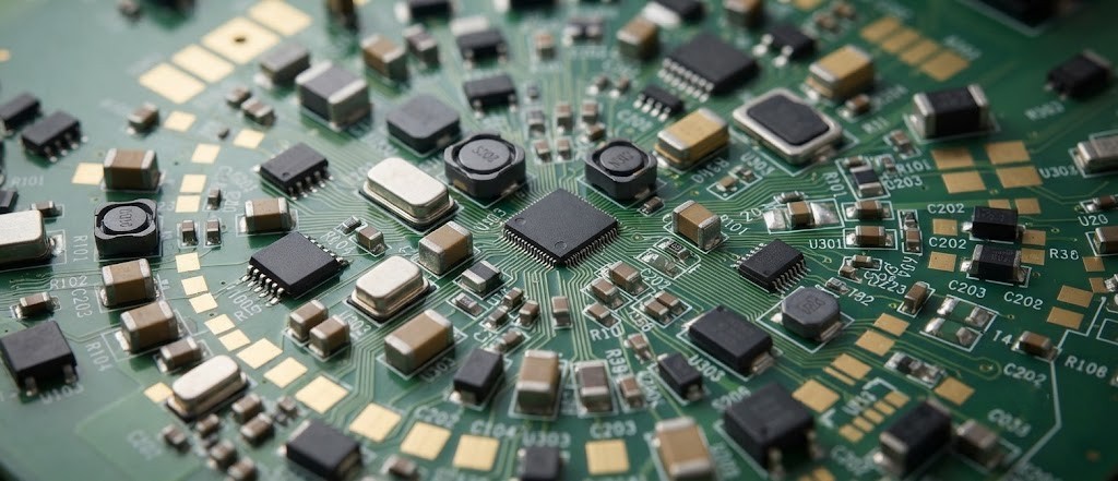
Each SMT machine has different limitations regarding component size, shape, weight, and feeding method. A single PCB may use a combination of 0201, 0402, and 0603 chips, transistors, ICs, QFPs, QFNs, BGAs, and larger components such as connectors. Small components require high-precision nozzles and vision systems, while large or unusually shaped components may require dedicated pick-up mechanisms and feeders. Therefore, manufacturers should not rely solely on general machine specifications. Instead, the actual BOM should be compared with the machine's capabilities, particularly the smallest and largest component sizes, package types, number of component part numbers, and feeding methods. If special components are overlooked during the initial evaluation, the machine may not be able to process the entire PCB. This can force the manufacturer to add additional equipment or continue using manual assembly after the production line has been commissioned.
2.2. Accuracy and repeatability
Accuracy indicates how closely the machine can place components to their target coordinates, while repeatability reflects its ability to maintain a consistent deviation over multiple cycles. For mass production, stability and repeatability are just as important as the stated accuracy. When evaluating an SMT pick-and-place machine, manufacturers should consider the calibration method, the vision system’s ability to recognize components, fiducial recognition, and the machine’s automatic position correction mechanism. A single accuracy figure in a catalogue should not be used as the sole basis for comparison, because measurement conditions and machine configurations may vary. If possible, the machine should be tested using actual PCBs and the production BOM. This is the most direct way to evaluate placement accuracy, component recognition capability, and machine stability before making an investment.
2.3. Placement speed vs. actual production output
“Machine speed” is often one of the first specifications considered when purchasing an SMT machine, but it is also one of the easiest to misinterpret. A machine may be rated for a very high placement speed under standard test conditions. In actual production, however, performance depends on the number of components, the travel distance of the placement head, component types, number of feeders, vision inspection requirements, and component layout on the PCB. Therefore, manufacturers should distinguish between theoretical placement speed and actual production output. Production requirements should be calculated based on the following sequence:
Required output → PCBs/hour → Components/PCB → Cycle time → Machine downtime → Changeover time.
For example, if a PCB requires a large number of components and contains many placement locations that require long head movements, a high nominal placement speed does not necessarily translate into equivalent production output. In addition, the overall production line may be constrained by processes before or after the pick-and-place machine. Even if the machine offers high placement speed, the total line capacity will still be limited if the solder paste printer, reflow oven, or inspection process cannot keep up. Therefore, manufacturers should evaluate the cycle time of the entire SMT line rather than optimizing the speed of a single piece of equipment.
2.4. Board size must account for panel dimensions
PCB dimensions determine the machine’s working area, board feeding method, and positioning capability. When evaluating an SMT pick-and-place machine, manufacturers should check both the minimum and maximum PCB dimensions, as well as board thickness, weight, and the PCB handling method used throughout the production line. One commonly overlooked factor is the panel. When multiple PCBs are assembled into a single panel for production, the dimensions that must be checked against the machine are the actual panel dimensions, not the dimensions of an individual board. For long, thin, or distortion-prone PCBs, the board support mechanism should also be considered. If the PCB becomes deformed during transportation or component placement, the accuracy of the entire process may be affected. Beyond the products currently in production, manufacturers should also consider PCB models planned for future production. A machine that is sufficient for today’s products but cannot accommodate the dimensions or panel configuration of future models can quickly become a capacity constraint for the entire production line.
2.5. Feeder capacity and changeover time
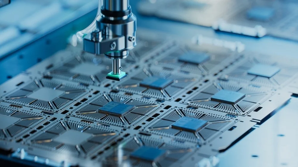
Feeders deliver components to the machine’s pickup position and typically use reels/tape, trays, or tubes depending on the component type. As the number of component part numbers on a PCB increases, the required number and types of feeders also increase. Therefore, manufacturers should compare the machine’s feeder capacity, feeding capability, and setup time against the actual BOM.
For factories producing multiple product models, changeover time can have a significant impact on productivity. Features such as storing programs for individual product models, preparing feeders offline, and scanning component codes to verify them against the production program can help shorten changeover time and reduce setup errors. Therefore, when comparing machines with the same CPH rating, manufacturers should not focus solely on placement speed. Setup efficiency and production flexibility should also be evaluated.
2.6. Production line connectivity and data management
An SMT machine needs to coordinate with other equipment in the production line, such as the solder paste printer, conveyors, reflow oven, and inspection systems, to maintain a continuous production flow. In addition, machine programs, component information, and production data can be stored and linked to product codes or production lots for quality control and traceability. If the manufacturer plans to implement MES connectivity or increase the level of production automation, data integration capabilities should be defined from the beginning. However, the connectivity configuration should match the actual scale and requirements of the factory to avoid investing in functions that will not be fully utilized.
2.7. Maintenance and technical support
Stable operation depends not only on machine specifications but also on maintenance, spare parts, and technical support. Components such as nozzles, filters, belts, and other consumable parts need to be inspected and replaced at appropriate intervals to minimize machine downtime. When selecting a supplier, manufacturers should consider technical response times, spare parts availability, maintenance documentation, and operator training. For integrated production lines, the supplier’s ability to provide support across mechanical, electrical, control, and software systems becomes even more important, because a failure in one piece of equipment can affect the entire production line.
3. Common mistakes when investing in an SMT pick-and-place machine
The most common mistake is choosing a machine based on the highest CPH rating. Nominal speed only indicates the machine’s capability under specific conditions, while actual production output also depends on the PCB, BOM, feeders, component layout, and setup time. A machine that is faster on paper does not necessarily produce more finished PCBs within the same production shift. The second mistake is evaluating the machine only based on current products. An SMT machine is a long-term investment, while products and BOM structures can change over time. If the configuration does not provide sufficient capacity for future board dimensions, feeder requirements, or component handling, the manufacturer may need to invest in additional equipment when new products are introduced.
Another common mistake is optimizing the pick-and-place machine independently without considering the balance of the entire production line. Final output is determined by the process with the longest cycle time or lowest capacity. Therefore, the SMT machine should be evaluated together with the solder paste printer, reflow oven, AOI system, and PCB handling system rather than as an isolated piece of equipment. For factories producing multiple product models, overlooking changeover time is another significant mistake. Part of the production time is not spent on component placement itself but on replacing feeders, preparing materials, loading programs, and verifying the setup. Reducing these periods can deliver significant productivity gains without increasing the machine’s mechanical placement speed.
Finally, manufacturers should not make an investment decision based solely on catalogue specifications. Testing the machine with actual PCBs and the production BOM makes it possible to evaluate component handling capability, speed, stability, and configuration suitability before making the final investment decision.
4. SMT pick-and-place machine solutions from CNC VINA
For manufacturers planning to implement or expand a PCB assembly line, CNC VINA can assess the products, production volume, and current processes to develop a suitable automation solution. Instead of selecting a machine based solely on its CPH specification, the solution should be determined based on the BOM, PCB dimensions, target output, cycle time, feeding method, changeover frequency, and inspection requirements. These factors provide the basis for determining the equipment configuration and its ability to integrate with the other processes in the production line. When assessing a project, the key information generally falls into four main categories: the products to be manufactured, required production output, production line organization, and future expansion requirements.
| Information Category | Key Information to Determine |
|---|---|
| Product | Dimensions, thickness, panel configuration, BOM, package types, and number of component part numbers |
| Production Capacity | PCBs/hour, components/PCB, cycle time, and target output |
| Operation | Feeders, setup time, inspection, and connectivity with existing equipment |
| Expansion | Future products, data integration capability, and production line upgrades |
For factories that do not need to automate the entire production line immediately, the implementation can be divided into multiple phases. Processes with high production volumes, stringent accuracy requirements, or a heavy reliance on manual operations can be prioritized first and expanded later as production volume and requirements change.
SMT pick-and-place machines should not be selected simply based on a single CPH figure in a catalogue. Equipment performance depends on its ability to handle the required component types, maintain placement accuracy, meet actual production requirements, and operate reliably with the entire production line. For factories producing multiple product models, factors such as feeder capacity, changeover time, program management, and data connectivity can be just as important as placement speed. In addition, technical service, spare parts availability, and upgrade capabilities have a direct impact on equipment stability throughout its investment lifecycle. CNC VINA can assess your products, production processes, and output requirements to recommend an automation solution suited to your factory’s specific operating model. Contact CNC VINA to discuss your requirements for an SMT pick-and-place machine and PCB assembly line solutions.
CNC VINA – VIETNAM TECHNOLOGY APPLICATION & CNC JOINT STOCK COMPANY
Factory: Song Cung Industrial Cluster, Dong Thap Commune, Dan Phuong District, Hanoi, Vietnam.
Office: Rox Tower Goldmark City, 136 Ho Tung Mau Street, Phu Dien Ward, Hanoi, Vietnam.
Phone: +84 916 639 355 / +84 915 744 664.
Website: www.cncvina.com.vn ; www.cncvina.net